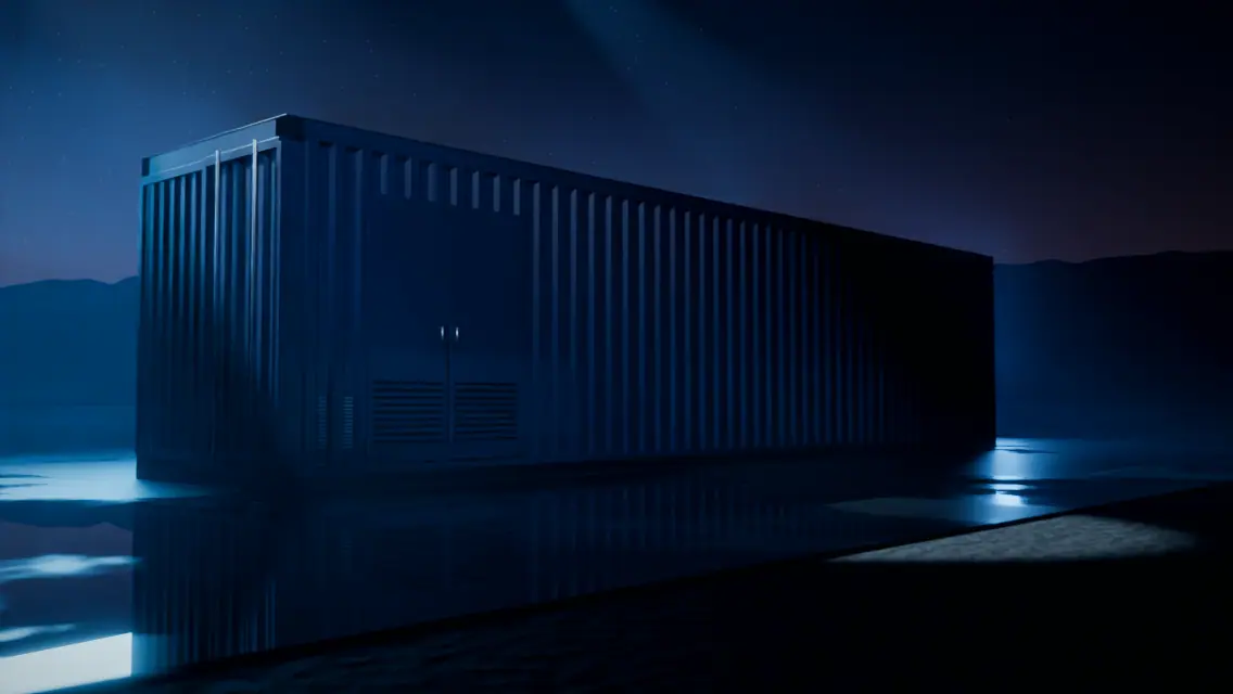
Louvered intake
Ambient desert air enters through louvered intakes along the container wall.


Illustrative image
Technology
Most atmospheric water generators chill air until moisture condenses, an approach that struggles as air dries out. Our platform captures moisture by absorption and releases it as water, a process designed for the low-humidity conditions of the American Southwest.
Why absorption
Refrigeration-style condensation needs air close to its dew point. In dry desert air, that means a lot of cooling for little water. Absorption-desorption works differently: moisture is captured from the air stream by an absorption stage, then released and recovered as liquid water.
| Approach | Conventional condensation | NextEra H2O absorption |
|---|---|---|
| Principle | Chill air below its dew point so vapor condenses | Capture moisture by absorption, release it, recover it as water |
| As air gets drier | Needs more cooling for each unit of water | Designed to keep working in low-humidity air |
| Designed for | Humid and temperate climates | Arid conditions like the American Southwest |
| Form factor | Varies | A containerized unit at the point of use |
Functional cutaway
Scroll through the seven stages, from ambient air at the intake to water in on-site storage. Tap a stage in the drawing to jump to it.
Schematic, not to scale. Zones show functional stages, not the exact internal layout or proprietary components. Flow lines are illustrative.
Ambient air is drawn in through louvered intakes along the container wall. The intake is the only “source” the unit needs: the humidity already present in the air.
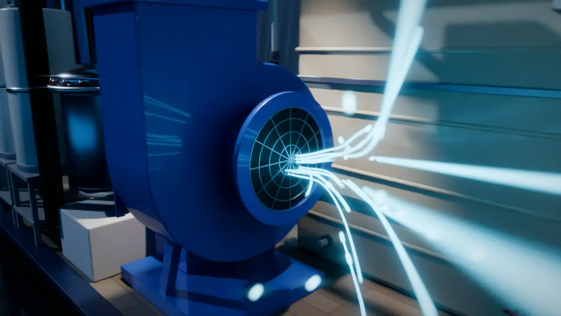
An air-handling blower moves a steady stream of ambient air through the unit. Airflow is one of the levers that shape how much moisture the unit can work with.
Moisture is captured from the air stream by absorption. This is the core of the platform: an absorption-desorption process designed for arid, low-humidity air, not a refrigeration condenser.
The captured moisture is released again (desorption) and recovered as liquid water through the unit’s water-recovery stage.
Recovered water passes through multi-stage filtration before it leaves the unit. Water-quality testing and permitting are handled per site and jurisdiction.
On-board controls run the cycle. Every installed unit is supported under a NextEra H2O service plan for maintenance and upkeep.
Water is held in an on-site reservoir and distributed where the customer needs it, at the point of use.
Schematic, not to scale. Zones show functional stages, not the exact internal layout or proprietary components. Flow lines are illustrative.
Scroll to approach the unit
Tap a step to jump to it, or tap a marker to see what that part does.
Shown as a 3D illustration based on the actual unit’s equipment.
How it works
Shown as a 3D illustration based on the actual unit’s equipment.
Components
Modeled on the actual unit’s equipment. Proprietary details are intentionally not shown.
Ambient desert air enters through louvered intakes along the container wall.
A blower and motor draw air into the unit and move it on through the ductwork.
Where moisture is captured and released in the absorption-desorption cycle.
Part of the water-recovery stage that turns released moisture into liquid water.
Recovered water is filtered through several stages before it leaves the unit.
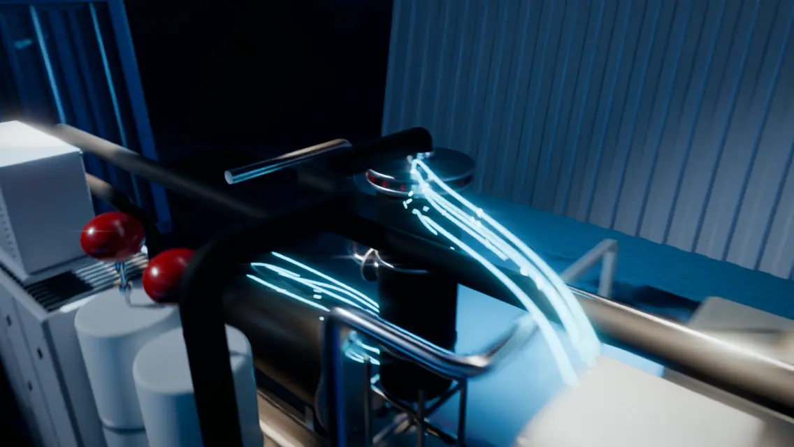
Process tanks on stands with expansion vessels above them, connected by insulated pipework.
The unit is grid-powered and sited at the point of use.
Every installed unit is supported under a NextEra H2O service plan.
What shapes output
How much water a unit makes depends on the air it works with and the site it sits on. We describe these factors qualitatively here; project-specific estimates come in a formal quote.
The amount of water vapor actually in the air is the raw material. It changes by season and by time of day.
Temperature changes how much moisture air can hold and how the cycle performs. Hot afternoons and cooler nights behave differently.
Unobstructed intake and exhaust, clear of recirculated air, help the unit see true ambient conditions.
The unit runs on grid power. A site’s power supply and conditions are part of every project estimate.
Filters and equipment kept in specification keep the unit performing as designed. Service is part of every deployment.
Monsoon months and dry spells differ. Projects are planned on annual averages, with the range disclosed.
How we report performance. Performance claims are a matter of measurement. U.S. pilots are intended to generate measured performance data at stated conditions; until then, figures are shared only with qualified parties under NDA, never as marketing numbers.
Water quality
Atmospheric water starts without the hardness and silica of ground and surface supplies. How the water is used, how it is tested and what is permitted is determined for each site and jurisdiction.


Next step
From data-center cooling makeup to community supply for modular homes, the same platform is sized to the site.